 | Image Processing and Analysis |
Distortion Evaluated from Tracking Data |
Fig2The amount of earth rotation during 26 sec required to scan an image results in distortion. |
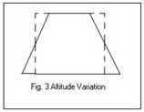
Altitude Variation (Fig.3)Distortion Evaluated from Ground Control |
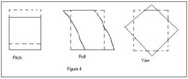
Attitude Variation - pitch, roll & yaw (Fig.4) |
|
|
|
|
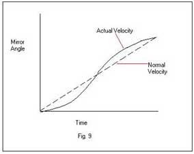
Mirror Velocity Variation |
Cross Track Distortion |
|
|
|
Remote Sensing |
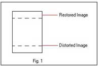
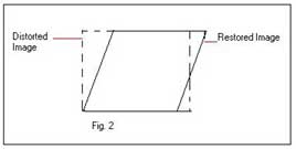
The amount of earth rotation during 26 sec required to scan an image results in distortion. The correction for this distortion can be done by scanning 16 successive group of lines, offset towards the west to compensate for the earth rotation, which causes the parallelogram outline of the restored image. Its is true for TM Image. (Fig.2)
Distortion Evaluated from Ground Control
Caused during the spacecraft scan of the ground .
Altitude Variation (Fig.3)
Correction Process for Non-systematic Distortions
Locating Ground Control Points This process employs identification of geographic features on the image called ground control points (GCPs), whose position are known such as intersection of streams, highways, airport, runways etc. Longitude and latitude of GCPs can be determined by accurate base maps where maps are lacking GPS is used to determine the Latitude and Longitude from navigation satellites. Thus a GCP is located in the field and determing its position using GPS. Accurate GCPs are essential to accurate rectification. GCPs should be
Reliably matched between source and reference (e.g., coastline features, road intersection, etc.)
Widely disperced throughout the source image
Resampling Methods The location of output pixels derived from the ground control points (GCPs) is used to establish the geometry of the output image and its relationship to the input image. Difference between actual GCP location and their position in the image are used to determine the geometric transformation required to restore the image. This transformation can be done by different resampling methods where original pixels are resampled to match the geometric coordinates. Each resampling method employs a different strategy to estimate values at output grid for given known values for the input grid.
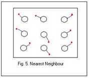
Nearest Neighbor The simplest strategy is simply to assign each corrected pixel, the value from the nearest uncorrected pixel. It has the advantages of simplicity and the ability to preserve original values in the altered scene, but it may create noticeable errors, which may be severe in linear features where the realignment of pixels is obvious. (Fig. 5).
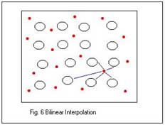
Bilinear Interpolation The strategy for the calculation of each output pixel value is based on a weighted average of the four nearest input pixels. The output image gives a natural look because each output value is based on several input values. There are some changes occurred when bilinear interpolation creates new pixel value. (Fig.6)
Brightness values in the input image are lost
As the output image is resampled by averaging over areas, it decreases the spatial resolution of the image
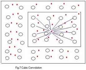
Cubic Convolution It is the most sophisticated and complex method of resampling. Cubic convolution uses a weighted average of values within a neighborhood of 25 adjacent pixels. The images produced by this method are generally more attractive but are drastically altered than nearest neighbor and bilinear interpolation.(Fig.7).
Image Correction using Mapping Polynomial Polynomial equations are used to convert the source coordinates to rectified coordinate, using 1st and 2nd order transformation . The coffiecients of the polynomial such as ai and bi are calculated by the least square regression method, that will help in relating any point in the map to its corresponding point in the image.
x0 = b1 + b2xi + b3yi
y0 = a1 + a2xi + a3yi
Where (xI yI ) are the input coordinates and (x0 y0 ) are the output coordinates.
Initially few GCPs cofficients are required to calculate the transformation matrix and the inverse transformation that could convert the reference coordinates of the GCPs back to the source coordinate system. This enables determination of RMS error for chosen transformation. The best order of transformation can be obtained using trial and error process while ignoring the highest RMS error from the least square computation.
Systematic Distortions
Geometric systematic distortions are those effects that are constant and can be predicted in advance. These are of two types:
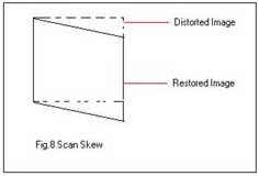
Scan Skew
It is caused by forward motion of the spacecraft during the time of each mirror sweep. In this case the ground swath scanned is not normal to the ground track. (Fig.8).
Known Mirror Velocity Variation
The known mirror velocity variation are used to correct the minor distortion due to the velocity of the scan mirror not being constant from start to finish of each scan line. (Fig.9)
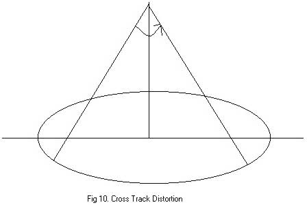
Cross Track Distortion
These generally occur in all the unrestored images accquired by the cross track scanners. They result from sampling pixels along a scan line at constant time intervals. The width of a pixel is proportional to the tangent of the scan angle and therefore is wider at the either margins of the scan line that compresses the pixel. This distortion is restored using trignometric functions.(Fig.10)
Systematic Distortions are well understood ands easily corrected by applying formulas derived by modelling the sources of distortions mathematically.
Atmospheric Corrections
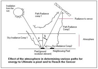
The output from the instrument on satellite depends on the intensity and spectral distribution of energy that is received at the satellite. The intensity and spectral distribution of energy/radiation has traveled some distance through the atmosphere and accordingly has suffered both attenuation and augmentation in the course of journey. The problem comes whenone is not able to regenerate the correct radiation properties of the target body on the earth surface with the data generated by the remote sensing
Effect Of The Atmosphere on Radiation (Radiative Transfer Theory)
Fig.11. Effect of the atmosphere in determining various paths for energy to illuminate a pixel and reach the sensor The path radiation coming from the sun to the ground pixel and then being reflected to the sensor. In this on going process, absorption by atmospheric molecules takes place that converts incoming energy into heat. In particular, molecules of oxygen, carbon-di-oxide, ozone and water attenuate the radiation very strongly in certain wavelengths. Scattering by these atmospheric particles is also the dominant mechanism that leads to radiometric distortion in image data
--------------------
Correcting For Atmospheric Scattering
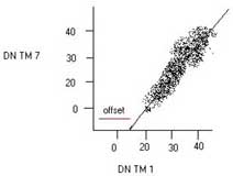
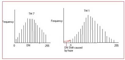
This correction is done when the two bands of image are subjected to ratio analysis. Atmospheric scattering scatters short wavelength and causes haze and reduces the contrast ratio of images. This follows two techniques for example TM bands 1 & 7, where TM 1 has the highest component of 1 and the TM7 (infrared) has the least. Both techniques are DN value dependent as TM band 7 is free from scattering effect there it has DN value either 0 or 1 (shadows).
In TM 7 the shadows having DN value 0 & 1. Now for each pixel the DN in TM 7 is plotted against TM 1 and a straight line is fitted through the plot using least square techniques. If there was no haze in TM 1 then the line would pass through the origin. But as there is haze the intercept is offset along the band 1. Haze has an additive effect on scene brightness. Therefore to correct the haze effect on TM 1, the value of the intercept offset is subtracted from the DN of each band 1 pixel for the entire image.(Fig 12)
The second technique also uses the areas with DN as 0 or 1 in TM 7. The histogram of TM 7 has pixels with 0 where as the histogram of TM 1 lacks the pixel in the range from 0 to 20 approximately because of light scattered into the detector by atmosphere thus this abrupt increase in pixels in TM 1 is subtracted from all the DNs in band 1 to restore effects of atmospheric scattering.(Fig 13)
The amount of atmospheric correction depends upon
Wavelength of the bands
Atmospheric conditions
Short wavelength cause more severe scattering. Humid, smoggy and dusty cause more scattering than clear and dry atmospheres.
Pre-Processing of the Remotely Sensed Images
When remotely sensed data is received from the imaging sensors on the satellite platforms it contains flaws and deficiencies. Pre-processing refers to those operations that are preliminary to the main analysis. Preprocessing includes a wide range of operations from the very simple to extremes of abstractness and complexity. These categorized as follow:
Feature Extraction
Radiometric Corrections
Geometric Corrections
Atmospheric Correction
The techniques involved in removal of unwanted and distracting elements such as image/system noise, atmospheric interference and sensor motion from an image data occurred due to limitations in the sensing of signal digitization, or data recording or transmission process. Removal of these effects from the digital data are said to be "restored" to their correct or original condition, although we can, of course never know what are the correct values might be and must always remember that attempts to correct data what may themselves introduce errors. Thus image restoration includes the efforts to correct for both radiometric and geometric errors.
Feature Extraction
Feature Extraction does not mean geographical features visible on the image but rather "statistical" characteristics of image data like individual bands or combination of band values that carry information concerning systematic variation within the scene. Thus in a multispectral data it helps in portraying the necessity elements of the image. It also reduces the number of spectral bands that has to be analyzed. After the feature extraction is complete the analyst can work with the desired channels or bands, but inturn the individual bandwidths are more potent for information. Finally such a pre-processing increases the speed and reduces the cost of analysis.
Radiometric Corrections
Radiometric Corrections are carried out when an image data is recorded by the sensors they contain errors in the measured brightness values of the pixels. These errors are referred as radiometric errors and can result from the
Instruments used to record the data
From the effect of the atmosphere
Radiometric processing influences the brightness values of an image to correct for sensor malfunctions or to adjust the values to compensate for atmospheric degradation. Radiometric distortion can be of two types:
The relative distribution of brightness over an image in a given band can be different to that in the ground scene.
The relative brightness of a single pixel from band to band can be distorted compared with spectral reflectance character of the corresponding region on the ground.
The following methods defines the outline the basis of the cosmetic operations for the removal of such defects:
Line-Dropouts
A string of adjacent pixels in a scan line contain spurious DN. This can occur when a detector malfunctions permanently or temporarily. Detectors are loaded by receiving sudden high radiance, creating a line or partial line of data with the meaningless DN. Line dropouts are usually corrected either by replacing the defective line by a duplicate of preceding or subsequent line, or taking the average of the two. If the spurious pixel, sample x, line y has a value DNx,y then the algorithms are simply:
DNx,y = DNx,y-1
DNx,y = (DNx,y-1 + DNx,y+1)/2
De-Striping
Banding or striping occurs if one or more detectors go out of adjustment in a given band. The systematic horizontal banding pattern seen on images produced by electro-mechanical scanners such as Landsat''s MSS and TM results in a repeated patterns of lines with consistently high or low DN. Two reasons can be thus put forward in favor of applying a ''de-striping'' correction :
The visual appearance and interpretability of the image are thereby improved.
Equal pixel values in the image are more likely to represent areas of equal ground leaving radiance, other things being equal.
The two different methods of de-striping are as follow:
First method entails a construction of histograms for each detector of the problem band, i.e., histograms generated from by the six detectors: these histograms are calculated for the lines 1,7,13,ģģ, lines 2, 8, 14, ģģ, etc. Then the means and standard deviation are calculated for each of the six histograms. Assuming the proportion of pixels representing different soils, water, vegetation, cloud, etc. are the same for each detector, the means and standard deviations of the 6 histograms should be the same. Stripes, however are characterised by distinct histograms. De-striping then requires equalisation of the means and standard deviation of the six detectors by forcing them to equal selected values - usually the mean and standard deviation for the whole image.
The process of histogram matching is also utilised before mosaicking image data of adjacent scenes (recorded at diferent times) so as to accommodate differences in illumination levels, angles etc. A further application is resolution merging, in which a low spatial resolution image is sharpened by merging with high spatial resolution image.
Second method is a non-linear in the sense that relationship between radiance rin(received at the detector) and rout (output by the sensor) is not describable in terms of a single linear segments.
Random Noise
Odd pixels that have spurious DN crop up frequently in images - if they are particularlt distracting, they can be suppressed by spatial filtering. By definition, these defects can be identified by their marked differences in DN from adjacent pixels in the affected band. Noisy pixels can be replaced by substituting for an average value of the neighborhood DN. Moving windows of 3 x 3 or 5 x 5 pixels are typically used in such procedures.
Geometric Corrections
Raw digital images often contain serious geometrical distortions that arise from earth curvature, platform motion, relief displacement, non-linearities in scanning motion. The distortions involved are of two types:
Non-systematic Distortion
Systematic Distortions
Rectification is the process of projecting image data onto a plane and making it conform to a map projection system. Registration is the process of making image data conform to another image. A map coordinate system is not necessarily involved. However rectification involves rearrangement of the input pixels onto a new grid which conforms to the desired map projection and coordinate system. Rectification and Registration therefore involve similar sets of procedures for both the distortions.
Non-Systematic Distortions
These distortions are caused due to variations in spacecraft variables. These distortion can be evaluated as follow:
see fig 1-4
Correction Process for Non-systematic Distortions see below http://educationally.narod.ru/gis3111photoalbum.html
Image Image Processing and Analysis
Correction Process for Non-systematic Distortions and continuety